始めたからには終わらせたいが,この記事は,そして僕は,どこに向かおうとしているのか。
ソース
All About Spines by Dave Tutleman
拙訳
さまざまなスパイン検知器 *1
フィールファインダー *2
もう何年も,「スパインファインダー」と呼ばれるクラブメイキングツールが市場に出回っている。私はこれを「ベアリングベースのスパイン検知器」と呼び,また人々がこれを「フィールファインダー」と呼んでいるのを目にしている。後者の方が好きだし,私もそれを採用している。(申し訳ない,その用語は誰が発案したのか分からない)。このテクノロジーは,Bill Dayが例の「用語集」の論文を書いたときに使ったものだ。*3
フィールファインダーはこのように働く:*4

自由に回転するボールベアリングの部品があって,そこにシャフトがはめ込まれる。そこでシャフトは自由に動く。ベアリングは直線状には配置されてなく(あるいは線上にならないようにすることができる――上図で赤い矢印が,ベアリングに働く力を示している),シャフトはベアリング部品の中で曲げられるかたちになる。そこでシャフトは回転するが,指でその回転を感じることができる。ここで,ふたつの特徴を感じることができる:*5
「バンプ」。この位置からシャフトは圧を得て,左右両方向に動く。これが一般的にはスパインと思われているもので,そのシャフトがいちばん硬い方向だ。*6
「安定した」方向。シャフトに外力が加わっていなければ,最終的に自然にその回転が落ち着く方向。ここから「NBP (natural bending position)」という名前が来ている。これは,曲げられたシャフトが落ち着きたい方向だ。*7
この原則として,ベアリングによって曲げられたシャフトが,その曲げを生む力を最小化する方向に,最終的に落ち着くだろうというものがある。それはいい原則だと思う。他の条件が同じから,これでシャフトがいちばん硬くない方向を見つけることができる。そうだとしたら,スパインフィアンダーズはスパインとNBPを検知する。*8
しかしときどき――実際にはしばしば――,他の条件は同じではない。シャフトに素のしなりがある場合,この計測はダメになる。その理由を見てみよう。*9

スパインがまったくないシャフト(つまり,あらゆる方向で硬さが同じシャフト)を考えてみよう。しかしこのシャフトには,上図の通り3mmの素のしなりがあるとする。3mmの屈曲は,それを探さない限り気づきはしないものだ。さて,このシャフトをフィールファインダーにかけて,20mm(約1インチ)しならせよう。*10

シャフトはフィールファインダーの中でスパッとポジションをとり,非常に強いスパインがあるように見える。しかしこのシャフトにはスパインがないことを仮定していたことを思い起こそう。どうしてこれが起こるのだろうか。*11

素のしなりがスパインファインダーに強いられた曲がりと同じ方向になるように回したら,シャフトは17mmだけしなる(20mmから素のしなりの3mmを引いたもの)。*12
その逆方向に回すと,シャフトは23mmしなる(20mmに素のしなりの3mmを加えたもの)。*13
これはしなり全体20mmのうちの6mmの差,あるいは30%の差だ。つまりそのシャフトは,ある方向に比べて別の方向に,よりしなる。実際,30%も多く。その結果,しならせるのに30%多く力を要する。なので,他の方向に比べてある方向により荷重がある。そしてその荷重の違いによって,フィールファインダーがスパインを特定する。*14
この荷重のせいで,シャフトの一方にスパインがあって,真逆の方向にNBPがあるという結論に至るだろう。しかしこの結論には2点の間違いがある:*15
ここではシャフトにスパインがないと仮定していたので,その点でこの結論は間違っている。*16
物理的に,もし一方にスパインがあれば,その真逆の方法にもスパインがあるはずで,NBPではない。なので,フィールファインダーは物理的にありえないことを物語っている。*17
これは,Bill Day が「タイプ1」と呼んだシャフト,つまり一方向にスパインがひとつあって,逆の方向にNBPがひとつあるシャフトを説明する。そしてこれはまた,これがスチールシャフトによく見られると彼が言う理由を説明する。スチールシャフトの多くがスパインがとても小さいので,素のしなりの影響がスパインのを上回るからだ。素のしなりだけが,フィールファインダーが計測できるものだ。*18
では,スパインと素のしなりとの両方がある場合はどうなるか? そのスパインの影響が素のしなりのものを上回るほどに大きくない限り,物理の法則に従わないようなスパインとNBPの方向とが見つかるだろう。そしてそれゆえ,間違っている。典型的な例をすぐあとで示す。実際,フィールファインダーの結果を信じられるのは,それがお行儀のいい「タイプ2」のシャフト,つまりふたつのスパインが180度の角をなして,ふたつのNBPが180度の角をなしていると,フィールファインダーが示しているときだけだ。もしそれ以外のことを示していたら,素のしなりに注意を払いすぎていて,間違った答えにたどりつくことになる。*19
フィールファインダーにはさまざまな形態があり,そのうちのいくつかは,単に感触に依るのではなく,定量的な計測もする。いくつかのバリエーションを見てみよう:*20

ベアリングがシャフト上に等間隔で配置される必要はない。多くの商業的フィールファインダーにはベアリングがふたつだけあって,それらは6インチから10インチぐらいの間隔があり,シャフトのバットが挿入される。これによって,この道具はひとつのチューブ内にふたつのベアリングがパッケージ化される。上の「JB spine finder」は,これのいい例だ。*21

シャフトのバットにふたつのベアリングが一緒にパッケージ化されるとき,第3のベアリングは手で持つかたちになる。あるいは第3のベアリングの必要もなく,ティップのベアリングの代わりに手を使うことになる。下図は,Jerry Ballard 自身が JB finder のデモをしているところだ。*22

しなりの分析機器として主に設計されているが,自身をスパインファインダーとも謳っているものも数多くある。その広告を見れば,それらは単にフィールファインダーのようなものではない,なぜならしなりによるシャフトへの荷重(シャフトの硬さの定義)を計測しているからだ,と信じてしまうかもしれない。*23
しかし,それらの形態をちらっと見れば,基本的には上の「原則」の図に一致することが分かるだろう。そして仮に同じスチールシャフト(スパインはなく3mmの素のしなりがある)をテストしたら,その機器はこう示すだろう――実際,とても正確に――,つまりこれは「タイプ1」のシャフトであって,30%のスパインがあると。なので,その出力結果がいかに正確であろうとも,その示された荷重のうちどれほどがスパインによるもので,どれほどが素のしなりによるものなのか,知ることは依然としてできない。*24
上の写真の「GolfMechanix Auditor」は,このタイプの機器のいい例だ。他にこの記述に合致するのは,「Flexmaster」「NeuFinder 2」「MCC Multi-Match」。それらのガジェットはフィールファインダーより正確だという弁明を聞いたことがある。実際そうだが。しかし,それより遥かに重要なことだが,スパイン検知に関していえば,それらがフィールファインダーより正しいことなど欠片もない。実際,正しくなんてまるでないのだ。(正確さと正しさとの違いで混乱されるようであれば,そのテーマに関する記事を読んでいただきたい。)*25
FLO
スパイン検知の「金字塔」であるFLO,ふたつの疑問を投げかける:*26
FLOは「Flat Line Oscillation(直線振動)」の略で,シャフトの振動が直線上で起こる,そのときの方向を指す。そうでないとき,シャフトはは直線を外れて(ぐらついて)振動する。*29

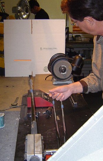
FLOをテストするためには,シャフトを振動数測定器に挟んで,ティップにおもりを乗せる(FLOを探すのに振動数メーターは必要ないが,しっかりとシャフトを挟んだ上で振動させる必要がある。そして振動数メーターであれば,容易にスパインとNBPを区別できる)。上の写真では,The Golf Coast の David Dugally がシャフトのティップにレーザーポインターを付けて,段ボールにシャフトの動きを映してトレースしている。その軌道はまっすぐな線だ。それが見たかったもので,それがFLOであるこを示している。シャフトが振動しているプレーンは,スパインプレーンかNBPプレーンかのいずれかだ。*30

もしそのシャフトに重大なスパインがあれば,ティップの軌道はもともとの直線から外れて,楕円のような形を描く――そのシャフトがスパインプレーンかNBPプレーン上を振動しているのでない限りは。なので,スパインかNBPを探すには,シャフトをさまざまな方向で振動させてみればいい。直線振動(FLO)を得られて楕円状にぐらつくことのないところが,振動のプレーンがスパインかNBPかになっている証拠だ。*31
FLOプレーンがスパインかNBPかは,振動数メーターで見る。そのうちの振動数の高い方がスパインだ(いざというときには,FLOプレーンががどちらかを知るのにフィールファインダーが便利かもしれない)。*32

この動画は,実際にシャフトがFLO外で動いている様子だ(クリックすると動画がダウンロードできる)。最初は上下に動くが,少し振動すると線を外れて軌道が「楕円」になる。しばし楕円に動いたあと,振動は少しのあいだだけ直線になるが,それはもともとの直線とは違う方向だ。それからさらに楕円になって,最初の直線上の振動に戻る。このシャフトにはとても顕著なスパインがある。多くのシャフトは軌道が直線から外れるのにもっと時間がかかる。*33
FLOが見つけるのは本当のスパインとNBPで,それは素のしなりのようなスパイン以外の要素に汚染されていないものだ。どうしてそうなるのか? もしシャフトがスパインかNBP以外の方向に曲がっていたら,結果のバネ効果はその曲がりにぴったりと沿うわけではない。それゆえに,振動の軌道がぐらつきはじめる。FLOプレーンを外れてしばらく振動させてみよう。するとそのぐらつきは明らかに目につくようになる。もしすべての詳細を知りたければ,別の記事をご覧いただきたい。*34
FLOを探すとき,ティップにつけるおもりは,それがしっかりとティップに固定されている限りはどんな重量でもいい。FLOプレーンはその重量に影響されない。そのおもりが中心を外れていても構わない。つまり,実際のクラブヘッドを付けてFLOのテストをしても,何ら変わりはないのだ。John Kaufman はこれを確認するために,ある面白い実験を行なった。以下は,CSFA Tech Notes から:*35
FLO vs. 重心*36 TECH NOTE 29: スパイン検知のプロセスにおいて,FLO(すなわちぐらつきがない状態)のふたつのプレーンを決定しようとする。これは非常に多くの場合,実際のクラブヘッドではなくティップにおもりをつけて行なわれる。起こる疑問としては,「ヘッドをつけたらFLOが変わるだろうか? なぜならヘッドの重心がシャフトの中心線からずれているから」というものだ。GolfSmithは,FLOは変わらないと言っている。それを知りたかった。もしFLOの変化が起こるとしたら,それは重心の変化に依るのだろうか,あるいはクラブをまっすぐ上下に弾くことができないからだろうか?*37 これをテストするために,とあるティップ用のおもりを作った。そのおもりの側面にアームを取り付けて,シャフトに付けられるようになっている。このピースはだいたい100グラムある。これによって,テスト用のウェイトの重心を1インチ以上ずらすことができる。ティップウェイトに非常に小さなキーチェーンレーザーを取り付けた。トリガーリリースシステムを作って,指で弾く際の不必要な変動を取り除いた。シャフトのバット側に10インチのディスクを置いた。このディスクには角度を測るための線があって,FLOを検知するあいだ,シャフトの置き方を繰り返せるようになっている。室内で20フィート先にレーザーを照射し,それでできるだけ正確にFLOプレーンを決定した。それからサイドウェイとを調節して重心を約1インチ動かした。FLOプレーンに違いはまったく見られなかった。GolfSmithは正しかったのだろう。*38
PUREDシャフト(ピュアリングしたシャフト)について聞いたことがおありだろう。そのシャフトは,SST PURE(Dick Weiss の会社)専用のマシンを使ってFLOが検知されたものだ。そのマシンはコンピューターがFLOプレーンを見つけるまでのプロセスを管理し,振動のブレを定量的に分析して,その詳細からFLOプレーンを推論する。そうするためには,振動の数理モデルが必要だ。幸運にも,スパインのあるシャフトの一方を固定したときの振動は,数理モデルが示すように,驚くほどにシンプルだ。そのモデルとそこからの帰結を,私のFLOに関する記事で読める。*39
FLOのセクションを終えるにあたって,これを繰り返す。つまり,FLOを検知するのは,それがスイング中のシャフトの動きの特性を示すにあたって重要だからではない。FLOを検知するのは,それがシャフトの最も硬い方向と最も軟らかい方向とを見つけるのに信頼できる方法だからだ。*40
差分しなり *41
FLOだけが,本当のスパインを見つける方法なのか? シャフトをしならせるのに必要な荷重を計測するのは,結果的に信頼できない答えになるのか?*42
必ずしもそうではない。シャフトをしならせるのに必要な荷重を計測するのは,実際にスパインを見つけるのには非常に真っ当なやり方だ。そしてそれは,スパインとNBPの定義に直結する。しかしそのためには,シャフトをあらゆる方向につねに同じ量だけしならせないといけない。フィールファインダーが信頼できないのは,素のしなりのあるシャフトは事前にしならされており,ベアリングベースのスパインファインダーでは上記のことができないからだ。*43
しかし,それを正しく行なえる機器も出回っている。それを正しく行なうために,すべての方向ですべての荷重に対して同じ量だけシャフトをしならせなければならない。シャフトには素のしなりがあるかもしれないので,これは一筋縄ではいかない。これをするためには,*44
シャフトを事前に少しだけしならせて,その荷重を記録する。*45
注意深くコントロールした量(これをDと呼ぶ)だけしなりを増やし,その荷重を記録する。*46
それらふたつの荷重の差が,Dのしなりによる荷重だ。*47
ふたつのしなりの荷重の差を用いているので,これは「差分しなり」と呼ばれる。ここで大事なのは,この計測では,(a) シャフトにはあらかじめ荷重され,すべてのポジションで結果を読み取らなくてはならない,(b) しなりDは非常に正確に再現可能である。ここでベアリングを用いることはできない。なぜならシャフトは各ポジションで,たとえシャフトが動きたがろうとも,しっかりと固定されていなくてはならないからだ。(フィールファインダーを使った経験から,シャフトはある方向でしならされたときに別のポジションに回転したがるのを知っている。)*48
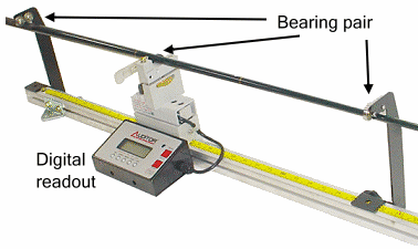
ここで,スパインとNBPとを差分しなりで検知する機器をいくつか紹介する。*49

「NeuFinder 4」(「NeuFinder 2」から2004年にアップグレードされた)は,差分しなりを想定して設計された。荷重の数値は,トグルレバーが事前荷重の状態から完全にしなる状態まで動いたときの荷重の増分を計測することで得られる。距離Dは事前負荷の状態の高さで設定され,計測器のこのカリブレーションが最も重要な部分である。*50
重要な点:シャフトはその中間部で,ベアリングではなくてV字ブロックの上に乗っている。これには十分な摩擦力があるので,シャフトが力を逃すような方向には動かない。上記の通り,差分しなりを機能させるためには,シャフトは各ポジションで動いてはならない。*51
「NeuFinder 4」には,差分しなりを計測するすべての機器と同様に,デジタル表示上に「Tare/zero」ボタンがある。なので,使用に当たって計算をする必要がない。シャフトに事前荷重をし,表示をゼロにし,それからシャフトをしならせる。そこで出る表示は差分しなりのものだ。引き算をする必要がない。*52
「Flexmaster」は差分しなりのスパイン検知に用いることができるが,注意事項がいくつかある:*53
取扱説明書を無視する必要がある。You have to ignore the instruction manual. Its instructions for spine-finding amount to a feel finder with a digital readout.
放っておくとシャフトはフィールファインダーNBPに回転する。回転しないようにおさえておく必要があるが,指の圧力が計測に影響しないように,慎重に行なわなければならない。*54
John Kaufman は自家製で差分しなり治具を作った。彼はこれを「Inverted Flex Board」と呼んでいる。これは非常にシンプルだ。Tare/zeroボタンのあるデジタルはかりを持っていれば,自分でも作ることができる。シャフトを支えるV字ブロックの下にスペーサー(毎回同じスペーサー)を加えることで,差分しなりDを再現可能にした。非常に賢い。*55
そこでこの質問が出てくる。「どの計測器を使って,そしてそれをどう解釈してスパインとNBPを検知するか?」*56

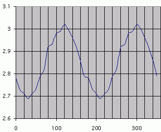
これは計測結果にサンプルだ。AJ Tech シャフトを用いて,10度ずつ計測していった。このシャフトから始めたのは,AJ Tech は非常に大きなスパインで知られており,このシャフトも例外ではないからだ。スパインとNBPを見つけるのは簡単なはずだ。*57
確かに,荷重とアングルの関係を示したグラフは,だいたい正弦波になっている。その山は120度と300度にあり,谷は30度と210度のところにある。スパインの定義は硬さが最大になる方向(山)であり,NBPの定義は硬さが最も弱るなるところ(谷)であるのを私たちは知っている。これは確かに,私たちが機械工学から学んだスパインのルールに合致している。*58
このグラフが滑らかな正弦波曲線になっていないのは,計測の不正確性に依るものだ。「NeuFinder 4」のデジタル計測結果表示は0.01単位になっており,正確さ(再現可能性)はたぶんそれ以上(0.01から0.02)だろう。それ以上に,10度以上にシャフトを正確に配置するのは非常に難しい。なので,正弦波は「ギザギザ」しているが,それはわずかな計測ミスのせいだ。これは,AJ Tech のようにスパインが顕著な場合は問題にならない。しかし……*59

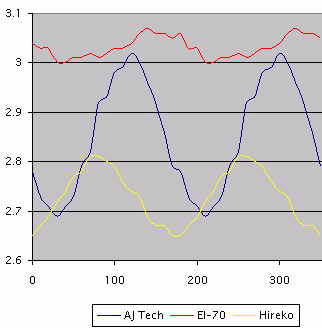
他のシャフトも用意した(比較のために AJ Tech も残している)。*60
Hirekoシャフトはスパインのサイズが AJ Tech の半分であり,読み取りやすいし,スパインの分布ルールにも即している。*61
True Temper EI-70 はHirekoの半分のサイズのスパインしかない。このシャフトでは,「ギザギザ」の影響が相対的に大きくなり,スパインとNBPとがどこにあるのか正確に読み取るのが難しい。他でやったように目視でそれをするのは,きっと不適切だろう。より洗練されたデータ分析が必要になるはずだ。あるいは,もっと良いのは,計測器の正確性を高めることだ。*62
なので,差分しなりには問題があり,それはスパインとNBPを見つけるためには正確な計測器とデータ分析が必要になるという点にある。*63
それ以外にも弱点がある。それは,FLO検知に比べてスパインとNBPを見つけるのに時間がかかるということだ。完全な測定値が必要になる。つまり,次のポジションに回して,事前荷重をし,目盛りをゼロにし,荷重し,新たに測定値を記録する。それをシャフトのすべての角度で行なう。10度間隔がたぶん正しいだろう。つまりそれは,データ分析を始めるまえに,18回の完全な計測を行なうことを意味する。*64
質問される前に答えておくが,イエス,事前荷重と目盛りの再設定を,毎回毎回行なう必要がある。そうしなければ,フィールファインダーと同じことをするにすぎない。*65
結論 *66
振動数メーター(あるいは単に適切な固定機)があるのなら,FLOはきっと最良にして最も手軽なスパイン検知方法だろう。*67
差分しなりはもっと時間がかかるし,スパインのサイズが小さいときは非常に正確にはならない。しかし,振動数メーターがなく,差分しなり機器があるのなら,努力に応じた正しい答えを出してくれる。*68
フィールファインディング――H.L. Mencken の言葉を借りるなら――は,手軽で,シンプルで,そして間違っている。シャフトに素のしなりがあれば,間違った方向を指し示す。そして,シャフトのスパインが小さければ,非常にクリアにスパインの方向を指し示すが,不幸なことに,それは素のしなりそのものに基づいている。これに価値があるとすれば,FLOを探す際のスタート地点を教えてくれることで,もし振動数メーターがなければ,どっちのFLOがスパインでどっちがNBPかのヒントにはなろう。*69
全記事
- スパインのすべて|エグゼクティブサマリー|The Tutelman Site - Linkslover
- スパインのすべて|Vol.1 - スパインとは何か/何ではないか|The Tutelman Site - Linkslover
- スパインのすべて|Vol.2 - さまざまなスパイン検知器|The Tutelman Site - Linkslover
- スパインのすべて|Vol.3 - スパインを探す:計器別の結果|The Tutelman Site - Linkslover
- スパインのすべて|Vol.4 - スパインアライメントの実験結果|The Tutelman Site - Linkslover
- スパインのすべて|Vol.5 - スパインアライメントの理論|The Tutelman Site - Linkslover
- スパインのすべて|Vol.6 - 未決事項|The Tutelman Site - Linkslover
- スパインのすべて|付録|The Tutelman Site - Linkslover
*1:Finding spines: the instruments
*2:Feel Finders
*3:For years, there have been clubmaking tools on the market called "spine finders". I refer to them as "bearing-based spine finders", and have seen them referred to as "feel finders". I like the latter term, and have adopted it. (Sorry, but I don't know to whom to attribute the term.) This is the technology that Bill Day was using when he wrote his "terminology" paper.
*4:Here is how feel finders work:
*5:A shaft is fit into three freely-rotating ball bearing assemblies, so it can rotate as it pleases. The bearings are not aligned (or can be forced out of line -- see the red force arrows on the picture), so the shaft must bend as it rests in the bearings. Now the shaft is rotated, and the fingers feel the rotation. There are two kinds of features that you feel:
*6:A "bump", a position where it takes some pressure to get the shaft there from either direction. This is generally considered to be a spine, the direction of maximum stiffness of the shaft.
*7:A "stable" direction, where the shaft rotates to naturally and rests there if not held. This is how the NBP got the name "natural bending position". It is the direction the shaft "wants" to rest if bent.
*8:The principle is that the shaft will naturally settle into the position that takes the least force to produce the bend imposed by the bearings. That's a good principle. All other things being equal, it will find the direction of least stiffness. Where that is the case, spine finders do find the spine and NBP.
*9:But sometimes -- often, in fact -- all things are not equal. If the shaft has any residual bend, it can throw off the measurement. Let's see why.
*10:Consider a shaft that has no spine at all (that is, the stiffness is the same in all directions), but 3mm of residual bend as shown in the picture. You would never notice 3mm of bend unless you looked for it. Now let's put the shaft in a feel finder that deflects the shaft by 20mm (almost an inch).
*11:The shaft will just snap into position in the feel finder, indicating a very strong spine. Remembering that we started out by saying there is no spine, let's understand why this happens.
*12:If you turn it so the residual bend is in the same direction as the spine-finder-induced bend, then the shaft is only deflected by 17mm (20mm minus the 3mm of built-in bend).
*13:If you turn it so the residual bend is in the opposite direction to the spine-finder-induced bend, then the shaft is deflected by 23mm (20mm plus the 3mm of built-in bend).
*14:That's a difference of 6mm, or 30% of the total 20mm bend. So the shaft is deflected more in one direction than the other direction. 30% more, in fact. The result: it will take 30% more force to deflect it. So there's a lot more force in one direction than the other. And that difference in force is how a feel finder locates the spine.
*15:Because of the forces as you turn the shaft, you will come to the conclusion that there is a spine on one side and an NBP directly opposite. There are two things wrong with this conclusion:
*16:We started out by saying the shaft has no spine, so the conclusion has to be wrong.
*17:We know from physics that, if there is a spine in one direction, the opposite direction will have a spine, not an NBP. So the feel finder is telling us something that is physically impossible.
*18:This explains what Bill Day calls a Type 1 shaft, a shaft with a single spine on one side and a single NBP opposite. It also explains why he says this is common in steel shafts. The vast majority of steel shafts have very little spine, so any residual bend will overwhelm what spine there is. The residual bend will be all that the feel finder can measure.
*19:What happens when there is both spine and residual bend? Unless the spine effects are large enough to overwhelm the residual bend, you will get spine and NBP directions that do not conform to the laws of physics -- and therefore are wrong. We will see typical examples a little later. Really, the only time you can trust the output of a feel finder is when it tells you that you have a well-behaved Type 2 shaft, with 180º between the spines and 180º between the NBPs. If it says anything else about the shaft, it is paying too much attention to the residual bend, and coming up with a wrong answer.
*20:Feel finders come in a wide variety of shapes, some of which use quantitative measures and not just the sense of feel. Let's look at a few variations:
*21:It is not necessary for the bearings to be equally spaced over the shaft. Many of the commercial feel-finders have two bearings only 6"-10" apart, for the butt of the shaft to be inserted. This allows the device to be packaged as two bearings in a tube. The JB spine finder at the right is a prime example of this very common construction..
*22:When the two bearings for the shaft butt are packaged together, the third bearing is often hand-held. Or it may be omitted altogether, leaving the fingers acting as the tip bearing. Here the JB finder is demonstrated by Jerry Ballard himself.
*23:There are quite a few instruments designed primarily as deflection analyzers, but which also advertise themselves as spine finders. One might be led by their advertising to believe that they are not just feel finders, because they measure the load on the shaft due to a deflection -- the definition of shaft stiffness.
*24:But one look at their configuration shows them to be identical to the "principles" diagram above. And, if we tested the same steel shaft (with no spine and 3mm residual bend), the instrument would tell us -- very precisely, in fact -- that it is a Type 1 shaft with a 30% spine. So, no matter how precise the output reading is, you still can't tell how much of the indicated load is the spine and how much is an artifact of residual bend.
*25:The GolfMechanix Auditor (shown in the photo) is a good example of this type of instrument. Others that fit the description are the Flexmaster, the NeuFinder 2, and the MCC Multi-Match. I have heard such gadgets defended as being more precise than feel finders. And they are. But -- much more important -- they are not a bit more accurate than feel finders, which is not very accurate at all. (If you are confused about the difference between precision and accuracy, see my article on the subject.)
*26:The "gold standard" for finding spine is FLO, raising two questions:
*27:What is FLO?
*28:Why does it find the spine better than other methods?
*29:FLO stands for "Flat Line Oscillation". It refers to the direction in which the shaft vibrates back and forth in a flat line, as opposed to wobbling out of the line.
*30:To test for FLO, place the shaft in a frequency meter clamp and weight the tip. (You don't need a frequency meter to find FLO, but you do need a very secure clamp and a tip weight to get the shaft to vibrate. And the frequency meter is handy to distinguish spine from NBP.) In the picture, David Dugally of The Golf Coast has attached a laser pointer to the tip of the shaft, so it traces out the path of the shaft on the cardboard in the background. The path is a nice, straight line. That's what you want to see; it indicates FLO. The plane in which the shaft is vibrating is either the spine plane or the NBP plane.
*31:If the shaft has a significant spine, then the path of the tip will wobble from its original straight line into an oval shape -- unless the shaft is oscillating in the plane of the spine or the NBP. So, to find the spine and NBP, test the vibration of the shaft in different orientations. Where you get Flat Line Oscillation with no tendency to wobble into an oval, then the plane of vibration is either the spine or the NBP.
*32:You can tell which FLO plane is the spine and which the NBP by using a frequency meter. The higher of the two frequencies is the spine. (In a pinch, a feel-finder may be useful to tell which FLO plane is which.)
*33:And here is an actual video of a shaft in non-FLO motion. (Click on the snapshot to watch the video.) It starts in a good up-down motion, but "ovals" out of it in a few vibrations. After ovaling a while, it briefly flattens again in a different direction from the original. But it ovals again before returning to the original up-down motion. This shaft has a very prominent spine; most will take longer to go out of flat.
*34:FLO finds the real spine and NBP, unpolluted by non-spine properties like residual bend. How does it do that? If a shaft is bent in any direction but a spine or NBP, the resulting spring force is not exactly in line with the bend. That causes the beginning of wobble. Let it vibrate outside the FLO plane for enough cycles, and the wobble becomes very visible. If you want all the details, they are available in another article.
*35:In finding FLO, you can use any convenient tip weight, as long as it is secured solidly to the shaft tip. The FLO planes will not change with the amount of weight. They won't even change if the weight is off-center -- which means there's no advantage to testing for FLO with the actual clubhead. John Kaufman did an interesting experiment to confirm this. From the CSFA Tech Notes:
*36:Flat Line Oscillation (FLO) vs Center of Gravity
*37:In the spine alignment process we try to determine the two planes in a shaft that produce flat line oscillation, i.e. no wobble. This is very often done with a tip weight rather than the actual clubhead. The questions arises," will the FLO change when I install the head because its center of gravity is offset from the centerline of the shaft?" Golfsmith claims it will not change. I was curious. If a change in FLO does occur is it due to the change in cg or because it's hard to twang the club straight up and down when your finger is twanging somewhere out on the clubhead rather than on the centerline of the shaft?
*38:To test this I built a tip weight with an arm sticking out of the side of the piece that attaches to the shaft. This piece weighed about 100 grams. I placed another weight on this arm and held it in place with a setscrew. This second weight also weighs about 100 grams. This arrangement allowed me to vary the cg of the test weight by more than an inch in a direction at right angles to the shaft. I attached a very small key chain laser to the tip weight. I built a trigger release system to eliminate any variations due to finger plucking. I placed a 10" disc on the butt end of the shaft. With degree lines on this disc it was easy to repeat alignments as I searched for the FLO. I determined the FLO plane as accurately as I could with the laser projected about 20 feet across the room. I then adjusted the side weight to move the cg about an inch. I did not find any variation in the FLO plane. I guess Golfsmith was right.
*39:You may have heard of PURED shafts. They are shafts whose FLO has been found using a proprietary machine from SST PURE (Dick Weiss' company). The machine uses a computer-controlled process to home in on the FLO plane by examining the wobble quantitatively and deducing the FLO plane from the details of the wobble. To do that, you need a mathematical model of the wobble. Fortunately, the vibration of a clamped shaft with a spine is remarkably simple as mathematical models go. You can see the model and a derivation of it in my article on FLO.
*40:Let's finish the section on FLO by repeating: One does not find FLO because FLO is important in characterizing the motion of the shaft during the swing. One finds FLO because FLO is a reliable way to find the stiffest and softest flex directions of a shaft.
*41:Differential deflection
*42:Is FLO the only way to find true spine? Does measuring the force needed to deflect the shaft always result in unreliable answers?
*43:Not necessarily. Measuring the force needed to deflect the shaft is actually a very sound way to find the spine; it goes right back to the definitions of spine and NBP. But you have to be sure you are deflecting the shaft by the same amount in all directions. The reason feel finders are unreliable is that a shaft with residual bend is pre-deflected, and bearing-based spine finders don't allow for that fact.
*44:But there are instruments around that can do it right. In order to do it right, you have to deflect the shaft by the same amount for every load reading in every direction. Since the shaft may have residual bend, this is tricky. The way to do it is:
*45:Pre-load the shaft by some small deflection, and note the load.
*46:Increase the deflection by a carefully controlled amount (call it D), and note the load.
*47:The difference between the two loads is the force due to a deflection of D.
*48:This is called "differential deflection" because you use the difference between the loads at two deflections. The important things in this measurement are (a) the shaft must be pre-loaded and "read" in every position and (b) the deflection D is very precisely repeatable. You can't use bearings for this, because the shaft must hold its position stably, even when it doesn't "want" to stay there. (We know from using feel finders that there are positions the shaft will rotate away from when deflected.)
*49:Here are a few instruments that can find spine and NBP via differential deflection:
*50:The NeuFinder 4 (a 2004 upgrade from the NeuFinder 2) was designed with differential deflection in mind. A load reading is taken by measuring the increase in load as the toggle lever moves from the pre-load stop to fully deflected. The distance D is set by the height of the pre-load stop, which is the most important part of the calibration of the instrument.
*51:Important point: the shaft is resting in a V-block instead of bearings at its middle support. This provides enough friction so the shaft will not roll to the direction of minimum resistance. As noted above, the shaft must stay put in each position for differential deflection to work.
*52:The NeuFinder 4, as all the instruments that do differential deflection, has a "Tare/zero" button on its digital readout. So you don't have to do arithmetic to use it. Pre-load the shaft, zero the readout, then deflect the shaft. The readout now shows the differential deflection -- no subtraction needed.
*53:The Flexmaster can be used for differential deflection spine finding, with a couple of caveats:
*54:The shaft will roll to a feel-finder NBP if you let it. You have to hold it to keep it from turning, which requires a careful touch to keep your finger pressure from affecting the reading.
*55:John Kaufman home-built his own differential detection jig, which he called an Inverted Flex Board. It's pretty simple. You could build one yourself if you have a digital scale with a tare/zero button. He makes the deflection distance D repeatable by adding a spacer (the same spacer every time) under the V-block that supports the shaft. Very clever.
*56:Which brings us to the question, "What measurements do you take, and how do you interpret them to find spine and NBP?"
*57:Here is a sample set of measurements. I have taken an AJ Tech shaft, and measured it at 10* increments. I selected this shaft to start because AJ Tech is known for very large spines, and this shaft is no exception. It should be easy to see and find the spine and NBP.
*58:Sure enough, the graph of load vs angle is roughly a sine wave. The peaks are at 120º and 300º, and the valleys at 30º and 210º. We know by definition that the spine is the direction of maximum stiffness (the peaks) and the NBP is the direction of minimum stiffness (the valleys). This certainly confirms the rules for the arrangement of spines that we learned from engineering mechanics.
*59:The graph is not a smooth sine wave because of imprecision in the measurement. The digital readout of the NeuFinder 4 has a resolution of 0.01, and a precision (repeatability) of perhaps a bit more than that (0.01 to 0.02). On top of that, it is very hard to align the shaft to a precision of better than 10º. So the sine wave has "jaggies" because of the slightly-off measurements. This is not a problem with a high-spine shaft like the AJ Tech, but...
*60:Here are a few more shafts. (I have left the AJ Tech there for comparison.)
*61:The Hireko shaft, with half the spine size of the AJ Tech, is still easy to read, and the spine distribution rules still hold true.
*62:The TrueTemper EI-70 has only half the spine size of the Hireko. For this shaft, the jaggies are big enough compared to the trend that it is difficult to tell exactly where the spine and NBP are. Doing it by eye, as we did with the others, is probably inadequate. We would need some more sophisticated data analysis. Or, even better, more precision in our instruments.
*63:So differential deflection has a problem in that it needs precise instrumentation and data analysis to find the spine and NBP.
*64:It has another weakness as well. It tends to take longer than FLO-finding to find the spine and NBP. You have to do a full reading -- that is, rotate to next position, pre-load, tare, load, record the reading -- for each angle of the shaft. 10* increments is probably right. That means 18 full readings for each shaft, before you begin the data analysis.
*65:Before you ask -- and everyone asks -- yes, you have to do a pre-load and tare for every reading. If you don't, you get the numbers that a feel finder would give.
*66:Bottom line
*67:If you have a frequency meter (or even just a proper clamp), FLO is probably the best and quickest way to find spine.
*68:Differential detection takes longer, and isn't very precise if the spine size is small. But, if you don't have a frequency meter and do have a differential deflection instrument, it gives correct answers for your efforts.
*69:Feel finding -- to paraphrase H.L. Mencken -- is quick, simple, and wrong. It gives wrong directions if the shaft has any residual bend. And, for shafts with small spines, it confidently gives very clear spine directions -- unfortunately based on little but the residual bend itself. Its major value is to give a starting point to look for FLO and, if you don't have a frequency meter, a hint which FLO is spine and which is NBP.